Books on the
bracing systems of buildings
|
|
|
|
|
|
Butterworth-Heinemann, 1992 |
E & FN Spon, 2000 |
CRC Press, 2013 |
CRC Press, 2020 |
|
Oxford, London, Boston… |
London and New York |
Boca Raton, London, New York |
Boca Raton, London, New York |



Stability of large structures – 1992; 2025 (2nd e-book edition)
Introduction
(K A Zalka)
Notations
(K A Zalka)
1 Background (G S T Armer) (1-6)
1.1 Preamble
1.2 Historical
development
2 Characteristics
of structural systems (G S T Armer) (7-22)
2.1 An
analysis
2.2 The
load-deformation characteristic
3 Design for
robustness (G S T Armer) (23-32)
3.1 Stability versus robustness
3.2 Current design methods
3.3 The prospects for current rules
4 System stability (G S T Armer) (33-38)
4.1 Safety in systems
4.2 Robust
systems
5 Continuum
method for regular frameworks under normal loading (K A
Zalka) (39-108)
5.0 Introduction
5.1 Assumptions
5.2 Substitute column
5.3 Frameworks on fixed supports
5.3.1 Frameworks subjected to concentrated forces at
top floor level
5.3.1.1
The continuum model
5.3.1.2
Axial deformation of the columns
5.3.1.3
Frameworks with variable cross-sectioned columns
5.3.2 Frameworks with UDL at floor levels
5.3.2.1
The continuum model
5.3.2.2 Axial deformation of the
columns
5.4 Frameworks on pinned supports
5.4.1 The continuum model
5.4.2 Frameworks subjected to concentrated forces at
top floor level
5.4.3 Frameworks with UDL at floor levels
5.5 Loading
5.5.1 Structures with concentrated loads and UDL
5.5.2 Correction for frameworks subjected to UDL
5.5.3 The effect of non-proportional loading
5.6 Accuracy analysis, characteristic deformations
and design examples
5.6.1 Frameworks on fixed supports
5.6.2 Frameworks on pinned supports
5.6.2.1
Frameworks with ground floor beams
5.6.2.2
Frameworks without ground floor beams
5.6.3 Non-proportional loading
5.6.4 Test results
5.7 Conclusions
6 Generalization of the continuum method
(K A Zalka) (109-142)
6.1 Non-proportional frameworks
6.1.1 Frameworks with columns of different
cross-section
6.1.2 Frameworks on pinned supports without ground
floor beams
6.1.3 Frameworks with longer first storey columns
6.2 Coupled shear walls
6.2.1 Coupled shear walls subjected to concentrated
forces
6.2.2 Coupled shear walls with UDL at floor levels
6.2.3 Design examples - accuracy analysis
6.2.3.1
Comparison with FE results
6.2.3.2
Test results
6.2.4 Conclusions
6.3 Cross-wall system buildings
6.3.1 Approximate solution
6.3.2 Design example
6.4 Analogy between frameworks and sandwich
columns
6.4.1
Cantilever with shear and bending deformation
6.4.2
Approximate solution
6.4.3
Exact solution
6.4.4
Application to frameworks
6.4.5
Numerical example
6.5 Supplementary remarks
6.5.1
Semi-rigid joints
6.5.2
Elasto-plastic analysis
6.5.3
Generalization
7 Spatial
analysis of regular structures under normal loading (K A
Zalka) (143-182)
7.1 Introduction
7.2 Substitute core
7.3 Uniformly distributed floor loads
7.3.1
The governing differential equations
7.3.2
Doubly symmetric layout
7.3.3
Singly symmetric layout
7.3.4
Unsymmetric layout
7.4 Concentrated load at roof level
7.5 Practical application
7.5.1 Formulae for the overall analysis of buildings
7.5.2 Design examples
7.5.2.1
System of support cores
7.5.2.2
A single support core
7.6 Supplementary remarks
7.6.1
Shear centre - centre of torsion
7.6.2
Pierced support elements
7.7 Conclusions
8 Appendices (183-228)
8.1 Additive theorems (K A Zalka)
8.1.1
Southwell’s theorem
8.1.2
Dunkerley’s theorem
8.1.3
The Föppl-Papkovics theorem
8.1.4
The Rankine formula
8.2 Derivation of the governing equation for
torsional buckling (K A Zalka)
8.3 Tables for torsional buckling (K A Zalka)
8.4 Mathematical modelling of test data (G S T
Armer)
8.4.1 Preamble
8.4.2 Introduction
8.4.3 The elements of Law
8.4.4 Numerical proofs
8.4.4.1
Units
8.4.4.2
Operational techniques for measurement
8.4.4.3
Scale of measurement
8.4.4.4
The problem of dimensions
8.4.4.5
Constants
8.4.5 Law structure
8.4.5.1
Function
8.4.5.2
Law class
8.4.5.3
Class 1 Laws
8.4.5.4
Class 2 Laws
8.4.5.5
Class 3 Laws
8.4.5.6
Higher Class Laws
8.4.6 Discontinuities
8.4.7 The representation of empirical data by a
simple law form
9 References
(K A Zalka) (229-238)
10 Bibliography
(K A Zalka) (239-246)
Author index (K A Zalka) (247-250)
Subject index (K A Zalka) (251-264)
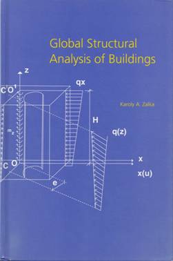
Global structural analysis of buildings – 2000
Preface
Notations
1 Introduction
(1-6)
1.1 Background
1.2 General
assumptions
1.3 The
structure of the book
2 Spatial
behaviour (7-17)
2.1 Basic
principles
2.2 The
equivalent column and its characteristics
2.3 The
spatial behaviour of the equivalent column
3 Stability
and frequency analyses (18-62)
3.1 Stability
analysis
3.1.1 Doubly symmetrical systems – basic critical loads
3.1.2 Coupling of the basic modes; combined sway-torsional buckling
3.1.3 Concentrated top load; single-storey buildings
3.1.4 Shear mode situations
3.1.5 Soil-structure interaction
3.1.6 Individual beam-columns
3.2 Frequency
analysis
3.2.1 Doubly symmetrical systems – basic natural frequencies
3.2.2 Coupling of the basic modes; combined
lateral-torsional vibrations
3.2.3 Concentrated mass at top level; single-storey buildings
3.2.4 Soil-structure interaction
3.2.5 Supplementary remarks
4 Stress
analysis: an elementary approach (63-97)
4.1 Horizontal
load
4.1.1 Wind
4.1.2 Seismic load
4.1.3 Construction misalignment
4.1.4 Comparisons
4.2 Buildings
braced by parallel walls
4.2.1 Basic principles
4.2.2 Load distribution
4.2.3 Deformations
4.3 Buildings
braced by perpendicular walls
4.3.1 Load distribution
4.3.2 Deformations
4.4 Buildings
braced by frameworks
4.4.1 Frameworks in a symmetrical arrangement
4.4.2 Frameworks in an asymmetrical arrangement
4.5 Maximum bending moments in the bracing
elements
4.6 Worked
examples
4.6.1 Example 1: building braced by parallel walls
4.6.2 Example 2: building braced by perpendicular walls
4.6.3 Comparison
4.6.4 Example 3: building braced by frameworks and a single wall
4.7 Discussion
5 Stress
analysis: an advanced approach (98-153)
5.1 The
equivalent column and its load
5.2 Deformations
of the equivalent column
5.2.1 Horizontal displacements
5.2.2 Rotations
5.3 Deformations
of the building
5.4 Load
distribution among the bracing elements
5.4.1 Shear forces and bending moments
5.4.2 Torsional moments
5.5 Stresses
in the bracing elements
5.6 Concentrated
force at top level; single-storey buildings
5.7 Buildings
with Ixy = 0, subjected to uniformly distributed
horizontal load
5.8 Worked
example: a 6-storey building in
5.8.1 Model: individual shear walls
5.8.2 Model: built-up shear walls and cores
5.9 Supplementary
remarks
5.9.1 Frameworks and coupled shear walls
5.9.2 Bracing systems with shear or a mixture of shear and bending
deformations
5.9.3 Special cases – scope for simplification
5.9.4 Second-order effects
5.9.5 Soil-structure interaction
6 Illustrative
example; Qualitative and quantitative evaluation (154-175)
6.1 Case
1
6.1.1 Critical load
6.1.2 Fundamental frequency
6.1.3 Maximum stresses and deformations
6.2 Case
2
6.2.1 Critical load
6.2.2 Fundamental frequency
6.2.3 Maximum stresses and deformations
6.3 Case
3
6.3.1 Critical load
6.3.2 Fundamental frequency
6.3.3 Maximum stresses and deformations
6.4 Evaluation
7 Global
critical load ratio (176-181)
7.1 Global
critical load ratio – Global safety factor
7.2 Global
critical load ratio – Performance indicator
7.3 Further
applications
8 Use of
frequency measurements for the global analysis (182-191)
8.1 Stiffnesses
8.2 Critical
loads
8.2.1 Multistorey buildings under uniformly distributed floor load
8.2.2 Concentrated top load; single-storey buildings
8.3 Deformations
8.3.1 Multistorey buildings subjected to horizontal load of trapezoidal
distribution
8.3.2 Concentrated force at top level; single-storey buildings
8.3.3 Deformations of the building
9 Equivalent
wall for frameworks; Buckling analysis of planar structures (192-237)
9.1 Introduction
9.2 Characteristic
deformations, stiffnesses and part critical loads
9.3 Frameworks
on fixed supports
9.3.1 The application of summation theorems
9.3.2 The continuum model
9.3.3 The sandwich model
9.3.4 Design formulae
9.4 Frameworks
on pinned supports
9.4.1 Frameworks without ground floor beams
9.4.2 Frameworks with ground floor beams
9.5 Frameworks
with ground floor columns of different height
9.6 Analysis
of coupled shear walls by the frame model
9.7 Frameworks
with cross-bracing
9.7.1 Shear stiffness and shear critical load
9.7.2 Critical loads
9.7.3 Structures with global regularity
9.8 Infilled
frameworks
9.9 Equivalent
wall for 3-dimensional analysis
9.10 Shear
walls
9.11 Symmetrical
cross-wall system buildings
9.12 Planar
bracing elements: a comparison
9.13 Supplementary
remarks
10 Test
results and accuracy analysis (238-253)
10.1 Description
of the models
10.2 Horizontal
load on Model ‘M1’
10.3 Horizontal
load on Model ‘M2’
10.4 Comparative
analysis of the formulae for horizontal load
10.5 Dynamic
tests
10.6 Stability
tests
10.6.1 Model ‘M1’
10.6.2 Model ‘M2’
10.6.3 Deformation of the bracing elements
11 Evaluation;
design guidelines (254-265)
11.1 Spatial
behaviour
11.2 Stability
analysis
11.3 Frequency
analysis
11.4 Stresses
and deformations
11.5 Structural
performance of the bracing system
11.6 Stability
of planar structures
11.6.1 Low-rise to medium-rise (4–25-storey) structures
11.6.2 Tall (over 25-storey) structures
11.6.3 Structural performance of planar bracing elements
Appendix A Cross-sectional characteristics for bracing
elements (266-277)
Appendix B The generalized power series method for
eigenvalue problems (278-282)
Appendix C Mode coupling parameter κ (283-314)
References
(315-324)
Further
reading (325-330)
Name index (331-334)
Subject
index (335-341)
Structural
analysis of regular multi-storey buildings – Hardback:
2013, paperback: 2017
Contents
Notations
1 Introduction (1-3)
PART I: THEORY (4-124)
2 Individual bracing units: frames, (coupled)
shear walls and cores (5-59)
2.1 Deflection
analysis of sway-frames under horizontal load
2.1.1 Basic behaviour; lateral deflection
2.1.2 Multi-storey, multi-bay frameworks
2.1.3 Discussion
2.1.4 Accuracy
2.2 Frequency
analysis of rigid sway-frames
2.2.1 Fundamental frequency
2.2.2 Discussion
2.2.3 Accuracy
2.3 Stability
analysis of rigid sway-frames
2.3.1 Critical load
2.3.2 Accuracy
2.4 Other
types of framework
2.4.1 Frameworks with cross-bracing
2.4.2 Frameworks on pinned support
2.4.3 Frameworks with columns of different height at ground floor level
2.4.4 Infilled frameworks
2.5 Coupled
shear walls
2.6 Shear
walls
2.7 Cores
2.7.1 Torsional stiffness characteristics
2.7.2 Deflection and rotation under uniformly distributed horizontal load
2.7.3 Critical load
2.7.4 Fundamental frequency
3 Deflection and rotation analysis of buildings
under horizontal load
(60-79)
3.1 Lateral
deflection analysis of buildings under horizontal load
3.2 Torsional
analysis of buildings under horizontal load
3.2.1 Torsional behaviour and basic characteristics
3.2.2 Torsional analysis
3.3 Maximum
deflection
3.4 Accuracy
4 Frequency analysis of buildings (80-97)
4.1 Lateral
vibration of a system of frameworks, (coupled) shear walls and cores
4.2 Pure
torsional vibration
4.3 Coupled
lateral-torsional vibration
4.4 Accuracy
5 Stability analysis of buildings (98-119)
5.1 Sway
buckling of a system of frameworks, (coupled) shear walls and cores
5.2 Sway
buckling: special bracing systems
5.2.1 Bracing systems consisting of shear walls only
5.2.2 Bracing systems consisting of frameworks only
5.2.3 Bracing systems consisting of shear walls and frameworks with very
high beam/column stiffness ratio
5.2.4 Bracing systems consisting of shear walls and frameworks with very
high column/beam stiffness ratio
5.3 Pure
torsional buckling
5.4 Combined
sway-torsional buckling
5.5 Concentrated
top load
5.6 Accuracy
6 The global critical load ratio (120-124)
PART II.
PRACTICAL APPLICATION: WORKED EXAMPLES (125-253)
7 Individual bracing units (126-140)
7.1 The
maximum deflection of a thirty-four storey framework
7.2 The
fundamental frequency of a forty-storey framework
7.3 The
critical load of a seven-bay, twelve-storey framework
7.4 The
critical load of an eight-storey framework with cross-bracing
7.5 The
critical load of eighteen-storey coupled shear walls
8 The maximum rotation and deflection of
buildings under horizontal load (141-157)
8.1 The
maximum deflection of a sixteen-storey symmetric cross-wall system building
8.1.1 Individual bracing units
8.1.2 Base unit. Maximum deflection
8.2 The
maximum deflection of a twenty-eight storey asymmetric building braced by
frameworks, shear walls and a core
8.2.1 Individual bracing units
8.2.2 Deflection of the shear centre
axis
8.2.3 Rotation around the shear
centre. Maximum deflection
9 The fundamental frequency of buildings (158-171)
9.1 Thirty-storey
doubly symmetric building braced by shear walls and frameworks
9.1.1 Individual bracing units
9.1.2 Lateral vibration in
direction y (Bracing Units 1, 2, 3 and 4)
9.1.3 Pure torsional vibration
(with all bracing units participating)
9.2 Six-storey
asymmetric building braced by shear walls and infilled frameworks
9.2.1 Lateral vibration in
direction x
9.2.2 Lateral vibration in
direction y
9.2.3 Pure torsional vibration
9.2.4 Coupling of the basic
frequencies
10 The global critical load of buildings (172-186)
10.1 Thirty-storey
doubly symmetric building braced by shear walls and frameworks
10.1.1 Individual bracing units
10.1.2 Sway buckling in directions
x and y
10.1.3 Pure torsional buckling
10.1.4 The global critical load
and critical load ratio of the building
10.2 Six-storey
asymmetric building braced by a core and an infilled framework
10.2.1 Individual bracing units
10.2.2 Sway buckling in directions
x and y
10.2.3 Pure torsional buckling
10.2.4 The global critical load
and critical load ratio of the building
11 Global structural analysis of a twenty-two
storey building (187-214)
11.1 The
critical load
11.1.1 Individual bracing units
11.1.2 Sway buckling in direction y
11.1.3 Sway buckling in direction x
11.1.4 Pure torsional buckling
11.1.5 Coupling of the basic
critical loads: the global critical load of the building
11.1.6 The global critical load
ratio
11.2 The
fundamental frequency
11.2.1 Individual units
11.2.2 Lateral vibration in
direction y
11.2.3 Lateral vibration in
direction x
11.2.4 Pure torsional vibration
11.2.5 Coupling of the basic
frequencies: the fundamental frequency of the building
11.3 Maximum
deflection of the building
11.3.1 Deflection of the shear
centre axis
11.3.2 Rotation around the shear
centre axis
11.3.3 The maximum deflection of
the building
12 The global critical load ratio: a performance
indicator (215-253)
12.1 Ten-storey
building braced by two reinforced concrete shear walls and two steel frameworks
12.1.1 The critical load of the individual bracing units
12.1.2 Case
1: an unacceptable bracing system arrangement
12.1.2.1 Stability analysis
12.1.2.2 Frequency analysis
12.1.2.3 Maximum
deflection
12.1.3 Case
2: a more balanced bracing system arrangement
12.1.3.1 Stability analysis
12.1.3.2 Frequency analysis
12.1.3.3 Maximum deflection
12.1.4 Case
3: an effective bracing system arrangement
12.1.4.1 Stability analysis
12.1.4.2 Frequency analysis
12.1.4.3 Maximum deflection
12.2 Five-storey
building braced by a single core
12.2.1 Layout A: open core in the right-hand side of the layout
12.2.1.1 Maximum rotation and
deflection
12.2.1.2 Fundamental frequency
12.2.1.3 Global critical load and
critical load ratio
12.2.2 Layout B: open core in the centre of the layout
12.2.2.1 Maximum rotation and
deflection
12.2.2.2 Fundamental frequency
12.2.2.3 Global critical load and
critical load ratio
12.2.3 Layout C: partially closed core in the right-hand side of the layout
12.2.3.1 Maximum rotation and
deflection
12.2.3.2 Fundamental frequency
12.2.3.3 Global critical load and
critical load ratio
12.2.4 Layout D: partially closed core in the centre of the layout
12.2.4.1 Maximum rotation and
deflection
12.2.4.2 Fundamental frequency
12.2.4.3 Global critical load and
critical load ratio
Appendix:
List of worksheets (254-257)
References
(258-262)
Index (263-269)
Structural analysis of multi-storey buildings – 2020 (substantially updated 2nd
edition of “Structural analysis of regular multi-storey buildings”)
In memory
of Lajos Kollár
Contents
Notations
1 Introduction (1-4)
2 Individual
bracing units: frames, (coupled) shear walls and cores (5-82)
2.1 Deflection
analysis of rigid sway-frames under horizontal load
2.1.1 Characteristic deformations
2.1.2 One-bay, multi-storey frames
2.1.3 Extension of the results:
multi-bay, multi-storey frames
2.1.4 Discussion and special cases
2.1.5 Worked example: two-bay,
ten-storey frame
2.2 Frequency
analysis of rigid sway-frames
2.2.1 Fundamental frequency
2.2.2 Discussion
2.2.3 Worked example: three-bay,
twenty-five storey frame
2.3 Stability
analysis of rigid sway-frames
2.3.1 A comprehensive method for the
stability analysis
2.3.2 Worked example: two-bay,
twenty-five storey frame
2.4 Other
types of frame
2.4.1 A simple method for the
stability analysis
2.4.2 Frames on pinned support.
Stability analysis
2.4.3
Frames with longer columns at ground floor level. Stability analysis
2.4.4 Frames with cross-bracing
2.4.5 Infilled frames
2.4.6 Worked example: fifteen-storey
frame with cross-bracing
2.5 Coupled
shear walls
2.5.1 The modified frame model
2.5.2 Worked example: three-bay,
thirty-storey coupled shear walls
2.6 Shear
walls
2.7 Cores
2.7.1 Torsional stiffness
characteristics
2.7.2 Deflection and rotation under
uniformly distributed horizontal load
2.7.3 Fundamental frequency
2.7.4 Critical load
3 Deflection
and rotation analysis of buildings under horizontal load (83-126)
3.1 Three-dimensional
behaviour
3.2 The
planar problem: lateral deflection analysis of torsion-free buildings
3.2.1
The governing differential equations of the problem
3.2.2 Method “A”: The simple method
3.2.3 Method “B”: The more accurate
method
3.3 The torsional problem
3.3.1 Torsional behaviour and basic
characteristics
3.3.2 Torsional analysis
3.3.3 Discussion and special cases
3.4 Maximum
deflection
3.5 Load
distribution among the bracing units
3.6 The
behaviour of buildings under horizontal load
3.7 Worked
examples
3.7.1 Maximum deflection of
twenty-eight storey symmetric building
3.7.2 Maximum deflection of
twenty-eight storey asymmetric building
4 Frequency
analysis of buildings
(127-159)
4.1 Lateral vibration of a
system of frames, (coupled) shear walls and cores
4.2 Pure
torsional vibration
4.3 Coupled
lateral-torsional vibration
4.4 Worked
examples
4.4.1 Fundamental frequency of
twenty-five storey symmetric building
4.4.2 Fundamental frequency of
twenty-storey asymmetric building
5 Stability
analysis of buildings
(160-205)
5.1 Sway
buckling of a system of frames, (coupled) shear walls and cores
5.2 Sway
buckling: special bracing systems
5.2.1 Bracing systems consisting of
shear walls only
5.2.2 Bracing systems consisting of
frames only
5.2.3 Shear walls and frames with
very high beam/column stiffness ratio
5.2.4 Shear walls and frames with
very high column/beam stiffness ratio
5.3 Pure
torsional buckling
5.4 Coupled
sway-torsional buckling
5.5 Concentrated
top load
5.6 Worked
examples
5.6.1 Critical load of twenty-storey
monosymmetric building
5.6.2 Critical load of
fifteen-storey asymmetric building
6 Global
structural analysis
(206-279)
6.1 The
global critical load ratio
6.2 Illustrative
example
6.3 Practical
application No. 1: Illustrative example
6.3.1 Basic characteristics
6.3.2 Case 1: an unacceptable
bracing system arrangement
6.3.3 Case 2: a more balanced
bracing system arrangement
6.3.4 Case 3: an effective bracing
system arrangement
6.4 Practical
application No. 2: Kollár’s classic five-storey building
6.4.1 Layout “A”: an open core on
the right side of the layout
6.4.2 Layout “B”: an open core in
the centre of the layout
6.4.3 Layout “C”: a partially closed core on the right side of the layout
6.4.4 Layout “D”: a partially closed
core in the centre of the layout
6.5 Practical
application No. 3: Ten-storey asymmetric building
6.5.1 Stability analysis
6.5.2 Maximum deflection
6.5.3 Fundamental frequency
7 Accuracy
and reliability
(280-306)
7.1 Basic
characteristics of the bracing units
7.2 Structural
analysis of individual bracing units
7.2.1 Maximum deflection
7.2.2 Fundamental frequency
7.2.3 Critical load
7.3 Structural
analysis of systems of bracing units
7.3.1 Maximum deflection of
symmetric, torsion-free bracing systems
7.3.2 Maximum deflection of
asymmetric bracing systems
7.3.3 Fundamental frequency
7.3.4 Critical load
7.4 Accuracy
with the nineteen worked examples
Appendix: List of worksheets (307-310)
References (311-315)
Subject index (316-322)
Author index (323)